- Home
- Companies
- REDOR sp. z o.o.
- Products
- Wastewater Pumping Mixers
Wastewater Pumping Mixers
MP and MPA pumping mixers. In the biological water treatment process, a waste water recirculation is required. The pumping (recirculation) mixers pump the waste water, in particular the activated sludge, between the nitrification and denitrification chambers in the biological processes applied at the treatment plants. They can be also used in other industrial and hydrologic plants in which big amounts of fluids and relative small elevation heads (in particular, losses in pipelines) must be pumped. In particular, they are suitable for pumping polluted media, which are difficult to pump for other pumps.
The pumping mixers can run in continuous or periodical mode, depending on the applied process. They are installed at sewage treatment plants at pipeline inlets or tank division plates. In this case, they can be equipped with non-return flap valves. Thanks to the mixer speed control using a frequency converter, its output can be adjusted depending on the real circumstances.
Operation properties of mixers are characterized by the following parameters:
- Output Q [m3/s]
- Usable lift height Hu [m]
The pumping mixers can be operated in fluids at max. temperature of 40C and submersion depth to 10 m.
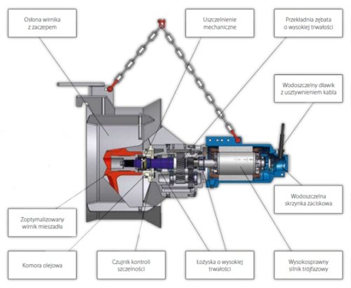
STRUCTURE
IMPELLER
- 3-blade, self-cleaning
MOTOR
- 3-phase, 400 V, 50 Hz, protection IP68, insulation class F, bimetallic sensors installed in each phase, 10 m power cable, synthetic protective coating. Motor is cooled by the surrounding liquid.
SEALING
- Impeller shaft is sealed with two seals. The outward seal (liquid side) is a mechanical face seal acting independently of the rotation direction; very high durability, made of silicon carbide or tungsten; on the motor side the impeller shaft is sealed by a lip seal.
BUFFERING CHAMBER
- It protects the motor against moisture from possible leakages.
PROPELLER SHIELD
- It is a cylindrical tube in which the impeller runs. Equipped with special fastenings for assembling the propeller to the pipe flange. The standard shield is made of galvanized steel sheet.
LEAKAGE DETECTION
- The mixer is equipped with an electronic leakage detection system. It indicates the presence of water in the buffering chamber.
Mixer impeller:
- brass
Motor body:
- cast iron Zl 250
Motor shaft:
- stainless steel
Mechanical seal:
- SiC / SiC or SiC / Co
Other seals:
- fluoric elastomer (FKM)
Screw joints:
- steel 1.4301
Impeller shield:
- standard version: steel 1.4301
STRUCTURE
IMPELLER
- 3-blade, self-cleaning.
MOTOR
- 3-phase, 400 V, 50 Hz, protection IP68, insulation class F, bimetallic sensors installed in each phase, 10 m power cable. Motor is cooled by the surrounding liquid. Synthetic protective coating.
REDUCTION GEAR
- 2 stage high-durability helical reducer, with cast iron body, lubrication with synthetic oil, output shaft and external stainless steel, synthetic protection coating.
SEALING
- Impeller shaft is sealed with two seals. The outward seal (liquid side) is a mechanical face seal acting independently of the rotation direction; very high durability, made of silicon carbide; on the gearbox side the impeller shaft is sealed using a lip seal.
OIL CHAMBER
- Filled with synthetic oil. This is an additional protection of the gear against moisture and any leaks.
PROPELLER SHIELD
- It is a cylindrical tube in which the impeller runs. Equipped with special fastenings for assembling the propeller to the pipe flange. The standard shield is made of galvanized steel sheet.
LEAKAGE DETECTION
- The mixer is equipped with an electronic leakage detection system. It registers the presence of water in the oil chamber.
Impeller blades:
- Epidian epoxy resin + glass fiber (laminate)
Propeller hub:
- steel 1.4021 (2H13)
Motor body:
- cast iron Zl 250
Gearbox body:
- cast iron Zl 250
Impeller shaft:
- steel 1.4028 (3H13)
Mechanical seal:
- SiC / SiC
Other seals:
- fluoric elastomer (FKM)
Screw joints:
- steel 1.4301
Impeller shield:
- standard version: steel 1.4301
There are two basic parameters for proper pumping mixer selection: required output Q [m3/s] and lift height H [m]
Mixer to be selected for parameters: Q = 0,32 m3/s, H = 0,71 m.
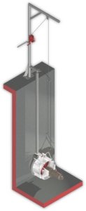
The supporting structure of pumping mixers consists of a single guide square cross-section form) fastened to a pass pipe situated in the tank wall and a bracket (at platform). The mixer is connected to the guide using a holder (integrated part of impeller shield) which enables the mixer to slide along the guide. Impeller shield is equipped with special fasteners. When the mixer is lowered in the tank, the fasteners fix it to the pass pipe flange. Therefore, it is important that the flange is made in accordance with DIN 2631 (PN6 flange). Flange drawing and dimension table see page 35.
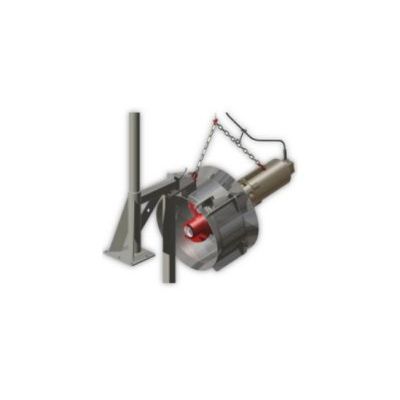
In the basic version, the submerged mixer is suspended on the crane rope. Here, a separate crane for each mixer must be installed (option 1). Mixer with chain fixed to the supporting structure, with additional rope for mixer removal using crane is also available (option 2). This way, the mixer can be removed from the crane foot and used for operation of other mixers. This variant is not recommended because the crane must be transported on treatment plant platforms (inconvenience).
All structure components are made of stainless or constructional galvanized steel. Due to price differences between these versions, exact agreement with the manufacturer on the materials for the individual supporting structure components is necessary (see supporting structure selection chart).
Supporting structure, standard scope of delivery
- Bracket / crane foot – 1 szt.
- Bracket assembling bolt set.
- Guide, length to 6m – 1 szt.
- Crane with winch – 1 szt.