The air-water solution is then passed through a saturation tank to allow additional time for the air to dissolve and to remove any coalesced air bubbles. The solution is then expanded across diaphragm control valves leading into WSI’s proprietary diffusers inside the body of the DAF. By reducing the pressure of the solution rapidly (expanding), the dissolved air is forced out of solution in the form of micro-bubbles (90% of the bubbles formed are less than 10 µm in diameter).
The small bubbles collect under the biomass floc and float it to the surface, forming a thickened sludge blanket on the surface of the DAF that is raked directly into a sludge holding tank. The DAF provides greater thickening of the sludge as well as a reduced footprint from a conventional clarifier. Settled sludge is periodically pumped to the sludge holding tank via progressive cavity pump.
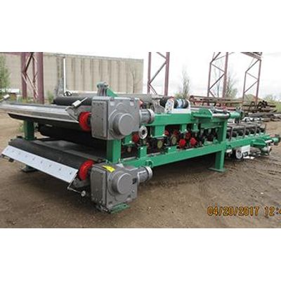
Stainless Steel Design
WSI DAF Systems, will be constructed from 3/16” stainless steel plate. The body is constructed with three independent cone bottom collection hoppers with pneumatically operated valve connection point. All process chambers of WSI DAF units are fabricated into the system. This includes: Two DAF floatation zones, scum collection hoppers with rail system, and effluent weir chamber.
Electrical & Controls
The system is provided with a main control panel that houses the Variable Frequency Drives (VFDs), motor starters, relays, Programmable Logic Controller (PLC) and Human Machine Interface (HMI). The VFDs are configured for the torque share operation mode. The panel enclosure is NEMA 4X with a side mount air conditioning unit to protect the control components in a wet, washdown environment. The HMI provides the press operational information in a graphical format to the operator and allows the adjustment of set points and parameters. The panel is provided with physical Hand-Off-Auto switches for all motors, enabling the system to be operated in an automatic mode as well as manually and overriding the logic controller.
When in automatic mode, the logic controller will flow pace the polymer injection rate to meet the operators desired dosage per feedback from the sludge magnetic flow meter.
Saturation Tank
The saturation tank is constructed from 304L Schedule 10 pipe and is designed and fabricated in such a way that coarse bubbles from the air enriching process are collected and discharge into the DAF effluent chamber. This prevents coarse bubbles from disrupting the sludge blanket that is formed in the floatation zone.
Micro Bubble Distribution
The Micro bubbles generated from the Nikuni pump system are dispersed into the DAF by three to six precisely located white water injectors. These injectors are constructed out of 1.5” schedule 10 304 stainless steel pipe. These pipes run the width of the DAF and have a proprietary grooved design opening for proper distribution and enhanced flocculation. Each injector has a diaphragm valve that will allow the operator to dial in the precise distribution of white water.