

- Home
- Companies
- ENERCALC, LLC
- Software
- ENERCALC - Calculation Modules
ENERCALC - Calculation Modules
The core of ENERCALC SEL (Structural Engineering Library) is its calculation modules. Dating back to 1982 when the Structural Engineering Library was released as a set of spreadsheet templates, our modules are designed as “fill-in-the-blanks” style of interactive programs. Simply type in a value and the resulting analysis or design is instantly there for your review.
All modules in the currently available build conform to:
- IBC 2021 / 2018 / 2015
- CBC 2019 / 2016
- ASCE 7-16 / 7-10
- ACI 318-19 / 318-14
- ACI 530-13
- TMS 402-16
- AISC 360-16 / 360-10
- NDS 2018 / 2015
The calculation module list is an ever-expanding set of structural calculations that provide analysis and design for the elements of a building. As requests are received from our users we develop additional modules…..and make use of the proven steel, concrete, timber, finite element analysis, and other engineering “solvers” we have developed.
Currently Included Modules:
Click on a module name to see a module-specific feature list
- Analyzes and designs up to 12 different non-composite beams within a single calculation item
- Permits wood, steel, and concrete beams
- Permits cantilevers to be modeled at one end or both ends
- Includes full wood and rolled steel section databases
- Allows fixed or pinned support conditions
- Incorporates point loads, concentrated moments, full-length uniform loads, partial-length uniform loads, and trapezoidal loads
- Includes option to perform automatic unbalanced live load placement (skip-loading)
- Incorporates either ASD or LRFD design methodology
- Offers the convenience of fill-in-the-blanks style forms and instantaneous recalculation to facilitate the evaluation of “what-if” scenarios
- Provides highly efficient results summaries as well as generous detail in the on-screen and printed results
- Provides sketch graphics to verify dimensions and load placement – including rich, 3D graphics that support zoom, pan, and many customizable view options. Example 3D image shown below.
- Provides shear, moment and deflection diagrams for all load cases
- Analyzes and designs individual non-composite steel beams
- Permits multi-span continuous beams
- Permits cantilevers to be modeled at one end or both ends
- Allows fixed or pinned support conditions
- Includes full rolled steel section database
- Incorporates point loads, concentrated moments, full-length uniform loads, partial-length uniform loads, and trapezoidal loads
- Includes option to perform automatic unbalanced live load placement (skip-loading)
- Incorporates either ASD or LRFD design methodology
- Considers user-specified allowable ratios for total load deflection and live load deflection
- Offers the convenience of fill-in-the-blanks style forms and instantaneous recalculation to facilitate the evaluation of “what-if” scenarios
- Provides highly efficient results summaries as well as generous detail in the on-screen and printed results
- Provides sketch graphics to verify dimensions and load placement – including rich, 3D graphics that support zoom, pan, and many customizable view options. Example 3D image shown below.
- Provides shear, moment and deflection diagrams for all load cases
- Analyzes and designs individual composite steel beams
- Includes full rolled steel section database and metal floor deck database
- Incorporates point loads, concentrated moments, full-length uniform loads, partial-length uniform loads, and trapezoidal loads
- Allows user to specify the timing of the application of individual loads with respect to the concrete achieving 75% of design strength
- Incorporates either ASD or LRFD design methodology
- Considers user-specified allowable ratios for total load deflection and live load deflection
- Offers the convenience of fill-in-the-blanks style forms and instantaneous recalculation to facilitate the evaluation of “what-if” scenarios
- Provides highly efficient results summaries as well as generous detail in the on-screen and printed results
- Provides sketch graphics to verify dimensions and load placement – including rich, 3D graphics that support zoom, pan, and many customizable view options. Example 3D image shown below.
- Provides shear, moment and deflection diagrams for all load cases
- Analyzes and designs individual non-composite steel beams
- Allows fixed or pinned support conditions
- Includes full rolled steel section database
- Incorporates point loads, full-length uniform loads, partial-length uniform loads, and trapezoidal loads at a specified eccentricity
- Incorporates concentrated moments causing bending or torsion
- Incorporates either ASD or LRFD design methodology
- Considers user-specified allowable ratios for total load deflection and live load deflection
- Offers the convenience of fill-in-the-blanks style forms and instantaneous recalculation to facilitate the evaluation of “what-if” scenario
- Provides highly efficient results summaries as well as generous detail in the on-screen and printed results
- Provides sketch graphics to verify dimensions and load placement – including rich, 3D graphics that support zoom, pan, and many customizable view options. Example 3D image shown below.
- Provides shear, moment and deflection diagrams for all load cases
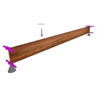
- Analyzes and designs individual sawn lumber, glulam, and manufactured wood beams
- Permits multi-span continuous beams, Permits cantilevers to be modeled at one end or both ends
- Allows fixed or pinned support conditions
- Includes sawn lumber and glulam databases, and a growing list of databases for manufactured wood products
- Incorporates point loads, concentrated moments, full-length uniform loads, partial-length uniform loads, and trapezoidal loads
- Includes option to perform automatic unbalanced live load placement (skip-loading)
- Incorporates either ASD or LRFD design methodology
- Considers user-specified allowable total and live load deflection ratios
- Provides highly efficient results summaries as well as generous detail in the on-screen and printed results
- Provides sketch graphics to verify dimensions and load placement – including rich, 3D graphics that support zoom, pan, and many customizable view options. Example 3D image shown below.
- Provides shear, moment and deflection diagrams for all load cases
- Analyzes and designs individual reinforced concrete beams
- Permits multi-span continuous beams
- Permits cantilevers to be modeled at one end or both ends
- Allows fixed or pinned support conditions, Permits up to six groups of reinforcing bars per span
- Capable of analyzing and designing rectangular, tee, H, and trapezoidal shaped sections
- Incorporates point loads, concentrated moments, full and partial-length uniform loads, and trapezoidal loads
- Includes option to perform automatic unbalanced live load placement (skip-loading)
- Considers user-specified allowable ratios for total load deflection and live load deflection
- Provides sketch graphics to verify dimensions and load placement – including rich, 3D graphics that support zoom, pan, and many customizable view options. Example 3D image shown below.
- Provides shear, moment and deflection diagrams for all load cases
- Analyzes and designs individual single-span masonry lintels
- Allows fixed or pinned support conditions
- Capable of analyzing and designing rectangular reinforced sections
- Incorporates point loads and uniformly distributed loads
- Incorporates either ASD or SD design methodology
- Offers the convenience of fill-in-the-blanks style forms and instantaneous recalculation to facilitate the evaluation of “what-if” scenarios
- Provides highly efficient results summaries as well as generous detail in the on-screen and printed results
- Provides sketch graphics to verify dimensions and load placement – including rich, 3D graphics that support zoom, pan, and many customizable view options. Example 3D image shown below.
- Provides shear, moment and deflection diagrams for all load cases
- Provides analysis capability (without design or code checking functionality) for an individual beam of specified section properties
- Permits multi-span continuous beams
- Permits cantilevers to be modeled at one end or both ends
- Allows fixed or pinned support conditions
- Incorporates point loads, concentrated moments, full-length uniform loads, partial-length uniform loads, and trapezoidal loads
- Includes option to perform automatic unbalanced live load placement (skip-loading)
- Offers the convenience of fill-in-the-blanks style forms and instantaneous recalculation to facilitate the evaluation of “what-if” scenarios
- Provides highly efficient results summaries as well as generous detail in the on-screen and printed results
- Provides rich, 3D graphics that support zoom, pan, and many customizable view options. Example 3D image shown below.
- Analyzes and designs individual steel columns
- Permits slenderness to be defined in a variety of ways, including the use of built-in non-sway alignment charts
- Allows various top and bottom support conditions
- Includes full rolled steel section database
- Considers combined axial load and biaxial bending
- Axial loads may be specified with or without eccentricity
- Lateral loads can be point loads, concentrated moments, full-length uniform loads, and partial-length uniform loads creating bending about either axis
- Incorporates either ASD or LRFD design methodology
- Offers the convenience of fill-in-the-blanks style forms and instantaneous recalculation to facilitate the evaluation of “what-if” scenarios
- Provides highly efficient results summaries as well as generous detail in the on-screen and printed results
- Provides sketch graphics to verify dimensions and load placement – including rich, 3D graphics that support zoom, pan, and many customizable view options. Example 3D image shown below.