
Fultek
Fultek - Version PLC -Fulmatic 7 -Programmable Logic Controller Software
FromFultek
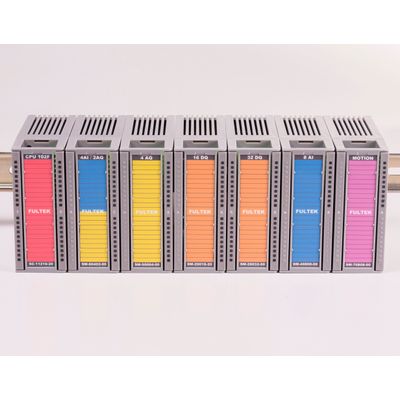
Fulmatic 7 – Series PLCs are the programmable control devices which are designed according to the automation needs by considering the tough conditions of the industry. Fulmatic 7 – Series PLCs are offered with 2 different memory options, 32KB and 115KB. All PLCs include Ethernet, Modbus TCP and minimum 1 RS485 Modbus RTU connection as well as webserver feature. The program can be installed into Fulmatic 7 PLCs in RUN state, it doesn’t requires switching to STOP state.
Most popular related searches
GENERAL FEATURES: Description
- Supply: 24V DC %15 tolerance band, 2,4W power consumption(standby)
- Digital Input / Output: Has 8 digital input and 8 digital output.
- Analog Input / Output: There is a different number of analog inputs and outputs according to the CPU model.
- RS 485: According to CPU model, there are 1 or 2 Rs485 port with 1200-230400 bps range.
- Modbus RTU support.
- Ethernet: 10/100 MBit Full dublex, DHCP support, WebServer support(10 socket), TCP Modbus support(5 socket), 512KB webserver file space.
- Program Loop Speed: Maximum loop count 65000 in a second.
- I/O Capacity: 512 Analog Input and 512 Analog Output or, 8192 Digital Input and 8192 Digital Output
- RTC: Real Time Clock (Runs 30 days without electricity.) Accuracy 3 seconds / Month @ 25 °C
- Working Conditions: -20 +60 °C / %5-95 Humidity
- The program can be installed while the PLC is running.
- The reasons for swithching the PLC to STOP state are monitored in the diagnostics section.
- High accuracy RTC(Real time clock) is standard for all models. It also works 30 days without energy supply. Battery does not used so it does not requires replacing the battery.
- The entire PLC memory can be used as ladder code or as persistent variables. You can use the 117760 Byte or 58880 Word variable in a single PLC.
- With additional modules, the 8192 Digital input or 512 analog input can also be extended to 8192 digital outputs or 512 analog outputs.
- Thanks to its rack structure, 63 additional modules can be added to the PLC. 4 racks can be made with rack connection module.
- Up to 32 Remote IO Cpu modules can be expanded. 4 racks can be added to each Remote IO Cpu module.
- The maximum number of modules available in a rack is 16. When 1024 modules are used, the PLC cycle time will still be below 5 milliseconds.
- With the Remote IO Cpu, remote IO modules can be controlled. Remote IO Cpu can be operate on Rs485 or Ethernet.
- Single PLC can respond to 17 devices simultaneously as 5 Modbus Tcp/Ip, 2 Modbus Rtu and 10 web client. At the same time, each device can read/write up to 256 bytes long data 60 times per second. The total duration of the query/response is about 16 milliseconds. At this time, the PLC cycle time will still be less than one millisecond.
- With a single PLC, 256 automatic PID and 256 PWM control can be made. In addition, with the 8-channel Motion module, 256 of 100 KHz PW or PTO outputs can be used in the single PLC.
- There are 256 software counter commands in one PLC. In addition, with the 8 channel counter(Motion) module, 256 units of 100 KHz counters can be used in single PLC.
- A single PLC has 256 timers with a resolution of 1 millisecond. The time-based interrupt block allows you to create thousands of software-based timers.
- You can create 256 program blocks and 256 function blocks in one PLC. Each block can have 32 networks. You can write 256 commands to each network.
- Function blocks can work with a pre-loaded parameter. For example, you can prepare a function block for motor control and call this block differently for thousands of motors. For each call, you just need to assign the variables of the respective motor.
- You can create 255 Data blocks in a single PLC. A data block can have a maximum length of 1024 bytes. DB0 is a 1024 byte length system data block. The first 345 bytes are used by the system. The other 679 Bytes are dedicated to your use. Program installation, PLC reset, firmware update or any other way DB0 is never deleted.
- The powerful Ladder compiler will compile almost any code you prepare. Restrictive situations do not occur, such as simple PLCs, such that input is not available after an output or output on each line.
- You can monitor the energy flow and variable values very quickly in the online ladder block monitoring screen. From this screen you can change the values of the variables.
- All models have 512Kb webserver space. All kinds of files can be stored in this field. You can also use the PLC program to store the user manual or project images. You can access it encrypted and unencrypted. Files uploaded to the Webserver will only be stored in the PLC and no other servers are needed. Clients over the local network or the Internet can access these files. You can upload large image files to different servers for using webserver’s memory efficiently.
- The hardware and safety features of the Fulmatic 7 Series PLCs are also at the highest level. All terminal connectors are protected. If 220-380 volts are not delivered incorrectly, the PLC will not be damaged. With 24 Volt you can connect all input outputs upside down, straight, short circuit or all other ways. Most will not work. You can even select analog inputs as 0-10 volts and use them as digital inputs with 24 volts. When 0-20 Ma is selected, the protection will be activated.
- Fulmatic 7 PLCs are capable of updating firmware via ethernet. In this way, you can get benefits of all updates. As with some PLCs, you will never see the message “This version cannot program this PLC”. Each update will be available in old PLCs as well.
- Fulmatic 7 PLCs are guaranteed for 2 years. Supply fails at 220 or 380 volts, water exposure or breakage with physical impacts is not covered by the warranty. Apart from these, we will only ask how its failed for improving our measures.