Glosfume
Glosfume - Ceramic Filter Elements
FromGlosfume
Ceramic Filter elements are manufactured at our factory in the UK by Glosfume Technologies Ltd. This allows Glosfume Ltd to maintain strict quality control with a capacity to manufacture 100,000 elements a year. When fitted to our new filter installations we offer a 2 year parts and labour guarantee. Unlike conventional ceramic elements, glosfume elements increase in strength when subjected to temperature.
Most popular related searches
ceramic filter element
filter element
ceramic filter
sodium bicarbonate
filter vessel
hot gas
PM2.5
activated carbon
filter cleaning
discharge hopper
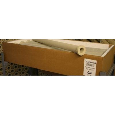
Sizes which are available tapered or parallel:
- 60mm O/D x 500mm long
- 60mm O/D x 1000mm long
Materials of construction and service temperature:
- Ceramic fibre1000°C
- Mineral fibre 700°C
- Soluble fibre 1300°C
Efficiency:
- 99.99%
Advantages over other high temperature filter elements:
- Stronger than any other low density ceramic filter element
- Micro porous finish removes particles as small as a nanogram
- Increase in strength when subjected to high temperatures
- Minimal Virgin pressure drop 25 mmWg @ 3 Cms
- Continuity in density for better performance
- Accurate machining of wall thickness for more consistent filtration
- Reinforced neck and end for greater strength
The Element life span is very much dependent on the process and can vary from one year up to six years.
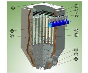
How it all works:
- The Element (1) hangs vertically from header plate (2) within the filter vessel. The header plate separates the filter`s clean and dirty compartments.
- Hot Gas is drawn through the filter medium (3) from outside to inside.
- Particulates and dry scrubbing sorbents are collected on the outer surface (4) of each filter element. These consist of the PM10, PM 2.5 size ranges; these agglomerate.
- The particles are removed from the element by reverse jet cleaning (5). This reversal causes the accumulated solids to be detached from the outer surface of the ceramic filter elements.
- The particulates and spent dry-scrubbing sorbents are discharged through the hopper outlet (6) for collection and disposal.
- The filter body can be protected with insulation (7) and trace heated (8) to prevent the formation of the condensation when the equipment is not in use.
- Incoming gas stream (9) and sorbent (if required).
- Outgoing cleansed gas stream (10)
- Injection point for activated carbon and/or sodium bicarbonate.